Solar Charger
Dec 3, 2015 · 3 mins read
A few months ago, I built a solar charger based on SparkFun’s Sunny Buddy and Adafruit’s Powerboost 1000.
The connections are pretty simple: a solar panel is connected to the Sunny Buddy, that charges a 2500mah lipo battery, on the output connection of the Sunny Buddy there is a Powerboost 1000 to convert the 3.7V from the battery to 5V USB, so that we can use it to charge mobile phones, smartwatches, batteries…
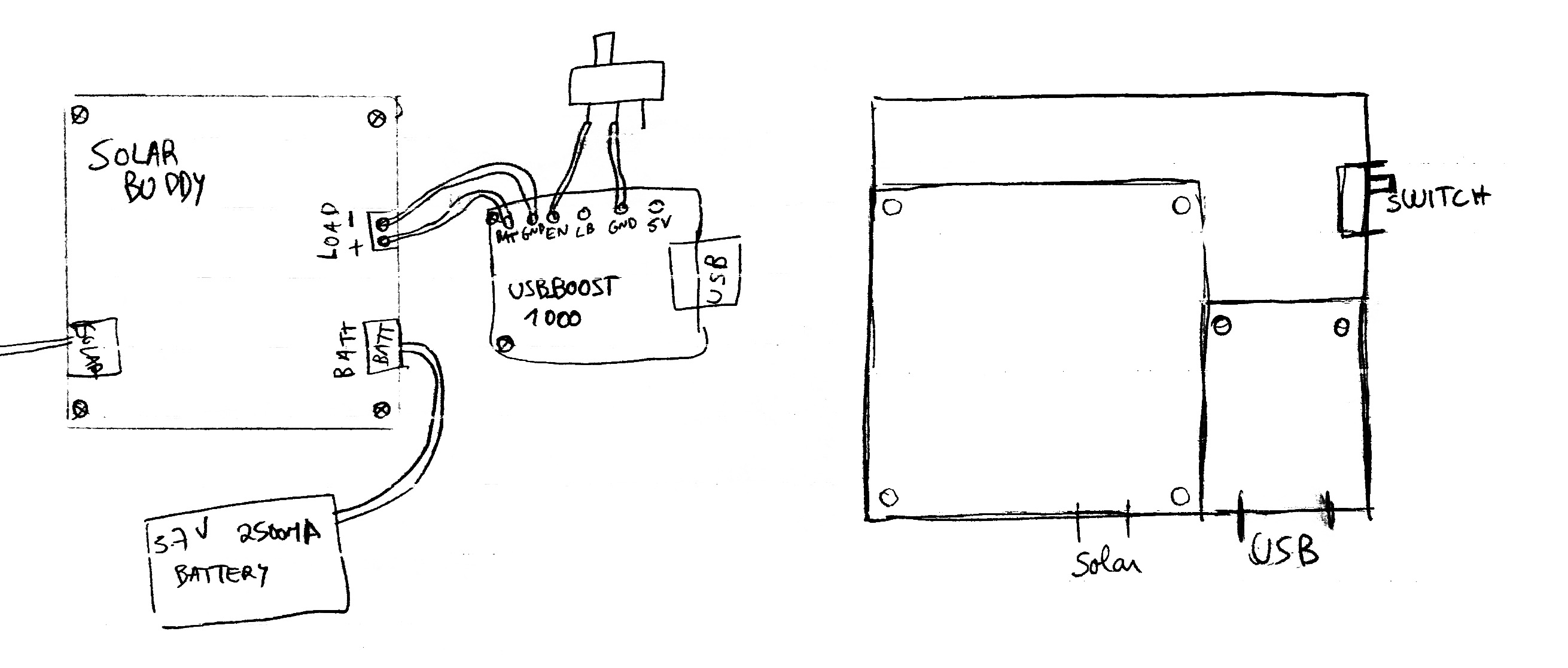 Schematic for Solar Charger
After figuring the correct pins for each connection, I soldered them with single core wires. To keep everything in place I drilled some holes on a clear piece of acrylic and used some nylon screws to attach the boards to it.
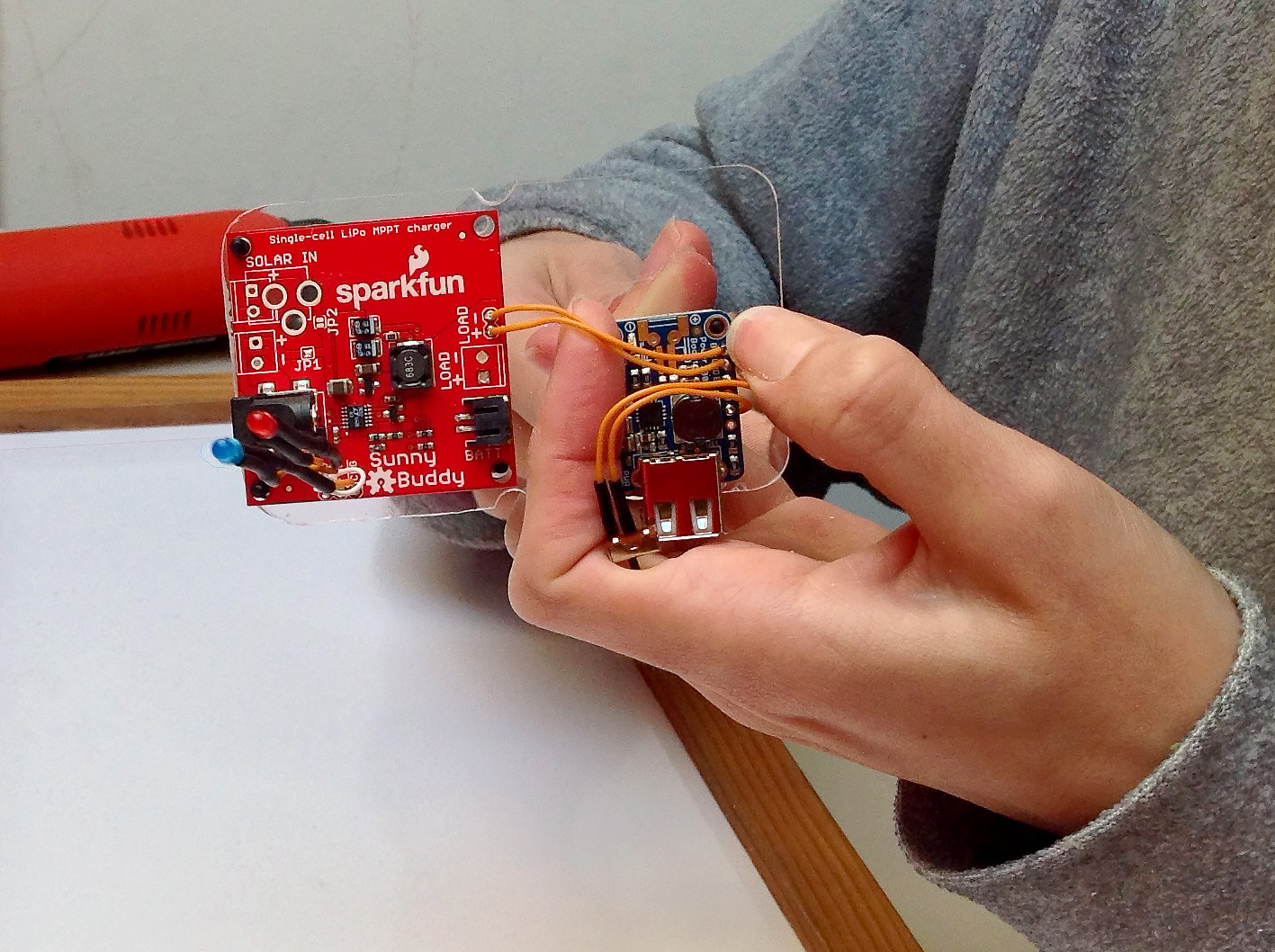 Acrylic PCB
I wanted to have a way to quickly check if the charger was working properly and if it was charging the battery or not (to find out how much sun light was needed for the charger to work). I sent an email to Sparkfun who answered me right away with a quote from the Datasheet with the combinations of the pins CHRG and FAULT and their meaning. However, when I connected an LED to CHRG and GND I was getting inconsistent values, that was because “CHG and FAULT are both open-drain active low devices, so they can’t drive an LED high” as informed by SFUptownMaker in a comment on the product page. To get the correct combinations I just had to change all the ON values to OFF and vice versa, and I got:
__________________________________________
|   CHRG    |   FAULT    |                 |
| (RED LED) | (BLUE LED) |                 |
|-----------|------------|-----------------|
| ON        | ON         | NOT CHARGING    |
|-----------|------------|-----------------|
| ON        | OFF        | BATTERY FAULT   |
|-----------|------------|-----------------|
| OFF       | ON         | NORMAL CHARGING |
|-----------|------------|-----------------|
| OFF       | OFF        | PAUSE           |
|___________|____________|_________________|
This way you can quickly see if there is something wrong with the charger, I also used the LED colors to make some sense of the meanings: Normal charging is BLUE, and Battery fault is RED. My father was particularly interested in this and every time he passed by the charger he checked if it was charging or not… :wink:
The circuit was all up and running, now it was time to build a case for it. I got this great looking case from eBay (it was actually a case to store fishing gear). I drilled some holes for the ports, and mounted all the components inside it.
 Solar Charger Box
Everything was perfectly fitted inside the case, the only thing left was gluing the switch for the Powerboost to the case, to keep it steady.
Sun, get ready to be squeezed!
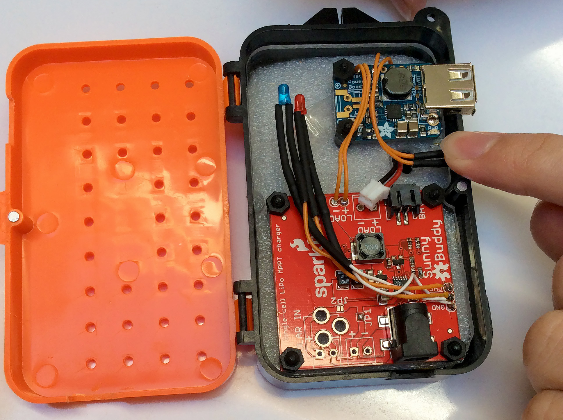 Inside the Box
I hope you liked this little post, I’ve since added some components to this solar charger and I’ve also built another!